Reflections on the Wunderkreis, 1

The Wunderkreis has often been the subject of this blog. Today I would like to bring some basic remarks to it.

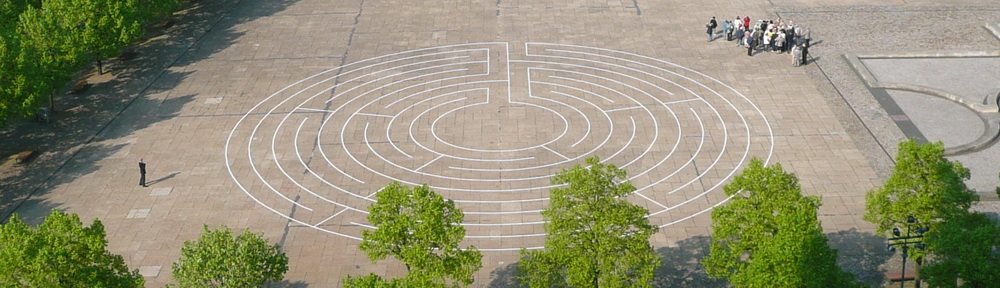
As is known, the Wunderkreis consists of labyrinthine windings and a double spiral in the center. Thus, there is no center to reach as usually in the labyrinth and, in addition, an extra exit, but it can also be formed together with the entrance in a branching.

This makes it more difficult to represent all this in a pattern. Also the usual path sequence (or circuit sequence) with the alternating odd and even numbers does not work properly anymore.

Therefore, I suggest to designate the spiral-shaped circuits with letters. This also gives the possibility to better describe the different types.

Here is the smallest Wunderkreis in my opinion:

Wunderkreis Type 3 a

A 3 circuit (normal) labyrinth with a double spiral. The path sequence, starting to the left, would be: 0-1-2-a1-a2-3-0. If I move to the right first, the result is: 0-3-a2-a1-2-1-0.

General note on “0”. This always means the area outside the labyrinth. Even if “0” does not appear on the drawings.

Now I can either increase the outer circuits or only the double spiral or both.

Type 3 a-b
Type 3 a-b

This is one more course for the double spiral. The path sequence to the left: 0-1-2-a1-b2-b1-a2-3-0. To the right: 0-3-a2-b1-b2-a1-2-1-0.

And now:

Type 5 a
Type 5 a

The double spiral as in the first example, the outer circuits increased by two. This creates a path sequence with (to the left): 0-3-2-1-4-a1-a2-5-0. Or to the right: 0-5-a2-a1-4-1-2-3-0.

Now follows:

Type 5 a-b
Type 5 a-b

In addition to the previous example, the double spiral is also enlarged. This results in: 0-3-2-1-4-a1-b2-b1-a2-5-0. And: 0-5-a2-b1-b2-a1-4-1-2-3-0.

In the circuit sequences I recognize the regularities as they occur also in the already known classical corresponding labyrinths. And if I omit the double spiral, I also end up with these labyrinths.

Related Posts

Crossing Labyrinths

Most of all labyrinths we know are alternating labyrinths. In these, the pathway does not traverse the main axis. Every time it arrives at the end of a circuit it changes direction and skips to another circuit. 

However, there exist some few labyrinths with the pathway crossing the main axis. This means, it does not change direction but only skips to an other circuit whilst following a piece along the axis. Up to now I simply have termed these „non-alternating“ labyrinths, since „alternating“ can be considered the rule. If we don’t want to term the property negatively („non-alternating“), we could also use terms such as „traversing“ or „crossing“. From now on, I will use the term „crossing labyrinths“ for such labyrinths. 

Whether a labyrinth is alternating or crossing, this refers to its main axis only. That is the axis where the entrance to the labyrinth and also the access to the center are situated. In labyrinths with one axis, there is only the main axis. Labyrinths with multiple axes, have also side-axes in addition to the main axis. Note that the pathway always must traverse the side axes. Otherwise, no side axes could be designed. 

Among the 87 types of labyrinths in my catalogue of historical labyrinths (see: further links, below), 10 are crossing, the others alternating. Here, I will show the three crossing labyrinths with one axis once more. All three have already been presented on this blog. 

The most remarkable crossing labyrinth is the labyrinth of St. Gallen. 

Figure 1. Labyrinth of St. Gallen

It has been repeatedly confused on this blog with the alternating labyrinth with 6 circuits and the same sequence of circuits, of which no historcal example is known (related posts 1 and 2).

Another very beautiful crossing labyrinth is the one by Al Qazwini (related posts 3). 

Figure 2. Labyrinth by Al Qazwini

The third crossing labyrinth with one axis is Folio 53r by Sigmund Gossembrot (related posts 4).

Figure 3. Labyrinth Gossembrot Folio 53r

All three are interesting crossing labyrinths, in which the pathway does not enter on the first circuit nor reach the center from the last circuit. In St. Gallen and Qazwini it traverses on the full distance of the axis, in Gossembrot 53r only one part of the axis (from the 6th to the 9th circuit).

Related Posts:

  1. How to Turn a Meander into a Labyrinth
  2. Listening to the Labyrinths
  3. The Labyrinth by Al Qazvini
  4. Sigmund Gossembrot / 5

Further links:

How to Make a 5 Circuit Knidos Labyrinth with one Rope

There is already something on this blog for a 3 or 7 circuit labyrinth. But not yet for a 5 circuit one.

As is well known, there are eight possibilities for a 5 circuit labyrinth (see Related Posts below). The best one for the purpose here seems to me to be the variant with the path sequence 0-5-2-3-4-1-6. Because in this case there are no crossing lines and it has only two turning points. That is, it consists of a single line. That is why it is best suited to be laid with a rope.

This is how the 5 circuit classical labyrinth in Knidos-style (with a larger center) might present itself:

The 5 circuit Knidos labyrinth

Below are some notes on the more precise construction method. For this, I have assumed an axis dimension of 50 cm (corresponding to the path width) and chosen four times this for the center. This results in a total diameter of 14 x 0.50 m = 7.00 m.
Here are the main elements first:

The construction elements

There are therefore a total of 3 midpoints around which the lines run in different radii. These must be determined first. Because they determine the appearance of the labyrinth. The entrance, the center and the orientation of the central axis.

Here are the associated dimensions for defining the three midpoints:

The dimensions
The dimensions

With this, starting from the center around M1 from M2 to M3 (or vice versa), the line can now be marked out, or the rope laid out.

The costruction drawing once again contains all the dimensions, as well as the radii of the various arch elements.

The construction drawing

Here is the construction drawing as a PDF file for download.


Now, if it’s about a certain labyrinth at a certain place, the dimensions can easily be changed. I can make the labyrinth larger or smaller. For this I have to calculate a scaling factor. How this is done will be explained in more detail.
If the labyrinth shall have a diameter of about 9.00 m, I calculate the scaling factor with 9.00 : 7.00 = 1.2857142. By multiplying with this factor I can determine all other dimensions. For the axis dimension (= path width), I would then have 0.50 x 1.2857142 = 0.6428571. This would also be the minimum radius for the curved sections. This is not very clever. 0.65 would be better, wouldn’t it? So I calculate a new factor with 0.65 : 0.50 = 1.3. Then I would have 7.00 x 1.3 = 9.10 as diameter and 67.75 x 1.3 = 88.075 as lines, or rope length. All other dimensions in the construction drawing would then have to be recalculated with this factor.

But if I have, for example, only one rope of about 55 m length, I would have to reduce the whole. The factor would be 55.00 : 67.75 = 0.8118081. The path width would then be 0.50 x 0.8118081 = 0.405904. This is again not so happy. I prefer to use 0.8 as a factor and get 67.75 x 0.8 = 54.2 m. The diameter would then be 7.00 x 0.8 = 5.60. Again, all other dimensions have to be recalculated accordingly.

So I can perform calculations according to different points of view.

Related Posts

Another Labyrinth with Pseudo Single-Barriers

In my previously shown labyrinths the pathway takes its course through all pseudo single-barriers in the same direction. In the pattern this course is from top left to bottom right, as shown in fig. 1 from my last post. Correspondingly, in the labyrinth, the path runs in clockwise direction from an outside circuit to a circuit more inside the labyrinth. 

Figure 1. Previous Courses of the Pathway

This raises the question whether other arrangements of the pseudo single-barriers are possible, such that the path may also take courses from inside out or in anticlockwise direction. In fig. 2, I show such a labyrinth. This is self-dual and has 4 axes, 9 circuits and 2 pseudo single-barriers in each side-axis. 

Figure 2. Labyrinth with 4 Axes, 9 Circuits and 2 Pseudo Single-Barriers at each Side Axis

Here, we have the following courses (fig. 3):

  • from top left to bottom right at the first axis upper barrier and at the third axis lower barrier
  • from bottom left to top right at the first axis lower barrier and at the third axis upper barrier 
  • from bottom right to top left at the second axis. 
Figure 3. Different Courses through the Single-Barriers

However, a course from top right to bottom left is missing.

Related Posts: