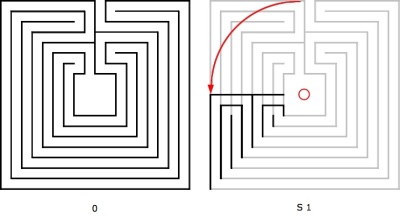
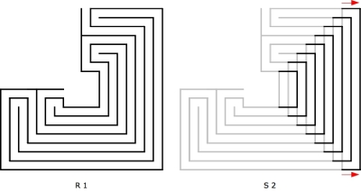
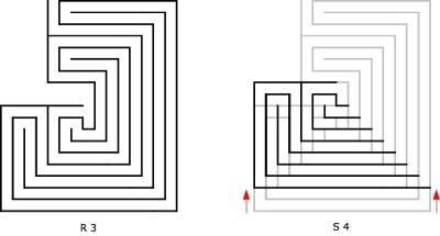
The Nîmes labyrinth is of the Cretan type although with a very special layout. The layout of the Cretan can be transformed in five steps to the Nîmes labyrinth. This is shown in the following illustrations. The figures on the left side show the starting point, whereas the right figures show the next step. In the right figures, the base situation is coloured in grey, the action in red and the result in black.
Ill. 1 shows the Cretan on a quadratic centered layout as the starting point (0). The center is somewhat enhanced; its height and width are 4 circuits wide. The reason for this is, that it enables us to bend all circuits 4 times by a quarter of a circle. By this, all opposite turns of the pathway are aligned along the axis and oriented vertically. (It is also possible to start with a rectangular layout with the center being 2 circuits high and 4 circuits wide. However, if we narrow the center to a size of 2 circuits in horizontal and vertical direction, the inner circuits of the labyrinth cannot be directed fully around the center and their turnpoints will be oriented horizontally.) As a first step (S 1), the opposite side of the axis is bent downwards 1/4 of an arc around the center in anticlockwise direction.
Ill. 2 shows the result of this step (R 1): A 3/4 labyrinth layout which does not cover the fourth quadrant. (Furthermore, the center is not closed, but this can be neglected here.) This result forms the starting point to the second step. In this step (S 2) we have to create space to be able to shift the inner circuits into the second quadrant. For this, the circuits have to be prolonged to the right by two units.
The result of the second step (R 2) can be seen in ill. 3. The labyrinth has now a rectangular (landscape) layout with wider interior space. In a third step (S 3), the lower circuits are shortened and the third quadrant is partly shifted into the interior space, so that the vertical wall between its 4th and 5th circuit aligns vertically with the upper axial wall.
Ill. 4 shows the result of this operation (R 3). Here, the final layout becomes recognizable. The center is still open, but one can guess how it will be closed. And this is what happens in the next step (S 4). For this, the lower half is shifted upwards by two units so that the lower horizontal bar comes to cover with the upper horizontal bar.
Ill. 5 now shows the labyrinth of Nîmes almost completed (R 4). It can be seen, that the exception, where the pathway makes the only additional bend of 1/4 of a circle before it reaches the center (see point 6 of my last post, related posts below), is a result of the transformation process. Now the only thing remaining is to prolong the four outer circuits upwards into quadrant 4, what is performed in the fifth step (S 5).
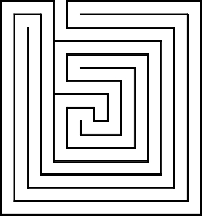
So, here we are. Ill. 6 shows the final labyrinth of Nîmes. All transformations only affect the layout of the labyrinth. None of the steps changes the level sequence of the pathway. Therefore the type of labyrinth remains the same throughout the whole transformation process.
Related posts:


